


!!!")


![]()
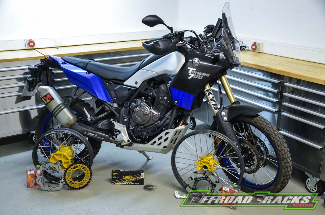
Nach der Vorstellung der High-End Räderpaarung (LINK) ist jetzt das Gabel-Update an der Reihe: Hier der erste Teil des Umbaus.
Für das Performance-Update an der Vorderhand werden wir eine 48er Upsidedown-Gabel montieren, die ein paar technische Leckerbissen erhalten wird. Doch bevor wir hier auf die Besonderheiten näher eingehen, wollen wir euch den Ausbau der Original-Gabel und den Einbau der Performance-Gabel im Detail näher bringen. Um diesen Umbau an einem Adventurbike mit 200 Kilogramm Startgewicht durchzuführen bedarf es ein paar Sicherheitsmaßnahmen, die im Fall einer leichten Sportenduro zwar nicht weniger wichtig sind, aber nicht ganz so in den Fokus rücken.
Für den Anwender: Hierbei handelt es sich nur um eine Hilfestellung, die sich fahrzeugspezifisch orientiert. Wer sich mit den erklärten Arbeitsschritten in Bezug auf seine eigenen Yamaha Ténéré 700 nicht hundertprozentig sicher ist oder nicht über die passenden Werkzeuge und die notwendigen Fachkenntnisse verfügt, sollte einen Fachmann zu Rate ziehen.
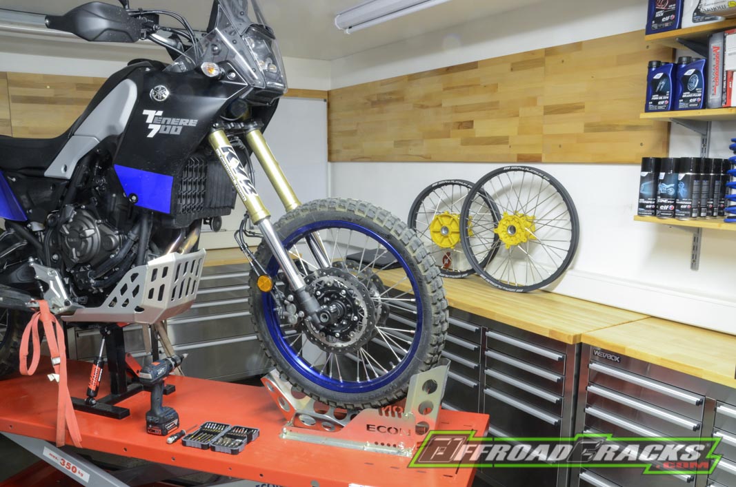
Wir bedienen uns in diesem Fall einer professionellen Hebebühne mit einem Hubständer, so dass die Räder entlastet werden und wir eine angenehme Arbeitshöhe realisieren können. Je nach dem wo der Hubständer angesetzt wird, stützt sich die Ténéré 700 kurz T7 automatisch auf dem Vorderrad oder dem Hinterrad ab. Da wir hier ein freies Vorderrad benötigen wird die T7 nochmal über das Hinterrad an der Hebebühne fixiert. Natürlich gehört das Sichern eines Motorrads auf einer Hebebühne immer dazu, was wir hier in klassischer Form über die Fußrasten vollziehen.
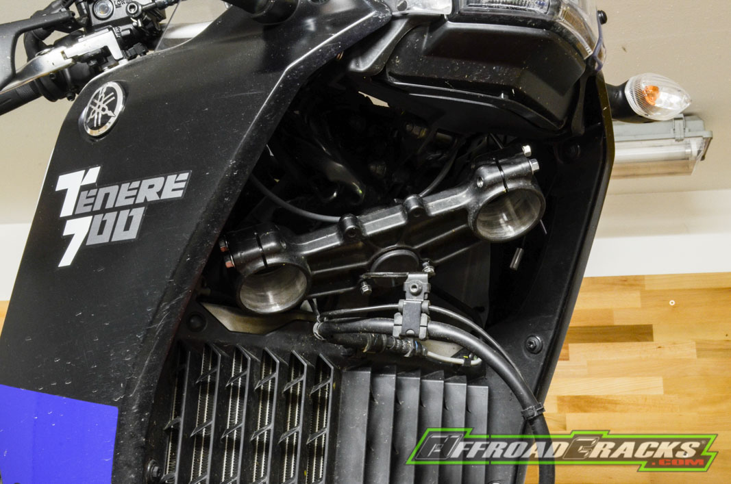
Für derartige Arbeiten sollte man auf ein etwas umfangreicheres Werkzeug-Sortiment samt Schrauber-Wissen zurückgreifen können, da der Gabel-Ausbau samt Gabelbrücke an einem Adventure-Bike etwas aufwendiger als bei einer Sportenduro ist. Zunächst müssen bei der T7 sechs Innensechskant-Schrauben an der vorderen Kunststoff-Radabdeckung entfernt werden. Wir nutzen hier einen Akku-Schrauber mit einstellbarem Drehmoment und Losbrechmoment, so dass man das Lösen und Festschrauben gut dosieren kann. Die sechs Innensechskant-Schrauben befinden sich einmal an den unteren Gabelfäusten sowie auf Höhe der seitlichen Halter mit Katzenaugen. Dann müssen nur noch die Bremsleitungen von ihren Kunststoff-Führungen auf dem hinteren Teil der Radabdeckung entfernt werden.
Anschließend heißt es den Tachogeber zu entfernen, der am linken Gabelfuß – in Fahrtrichtung – befestigt ist. Dieser ist gut geschützt durch einen Kunststoff-Protektor und kann nach Entfernen der Schraube einfach aus seiner Führung herausgezogen werden. Dann lässt sich das Verbindungskabel leichter von der Vorderradabdeckung lösen, so dass Letzteres komplett abgenommen werden kann, ohne dass es in seine Einzelteile zerlegt werden muss.
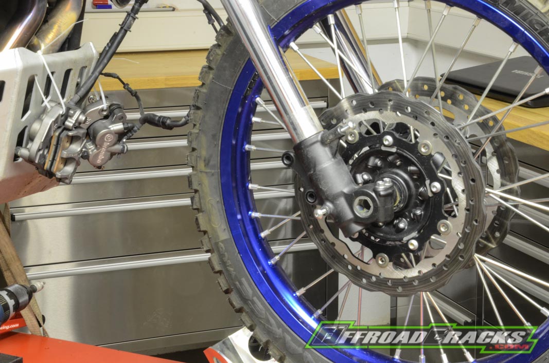
Die nächste Maßnahme gilt den Bremssätteln. Hierzu sollt man sich vorab ein paar Kabelbinder zur Seite legen. Zur Demontage benötigt man eine 12er Stecknuss sowie eine Ratsche mit kurzer Verlängerung, um die zwei Bremssattelschrauben lösen zu können. Diese sind meist mit einem etwas höheren Drehmoment verschraubt, weshalb man die Gabel links oder rechts auf Anschlag bringt, so dass sich diese nicht mehr selbst bewegen kann. Bevor man die letzte Schraube herausnimmt sind die Bremssättel mittels Kabelbinder am Unterfahrschutz zu sicheren, so dass kein unerwünschter Zug auf die Bremsleitungen kommt.
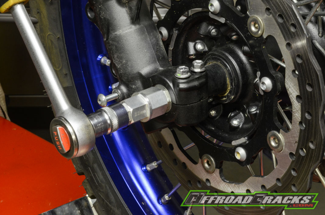
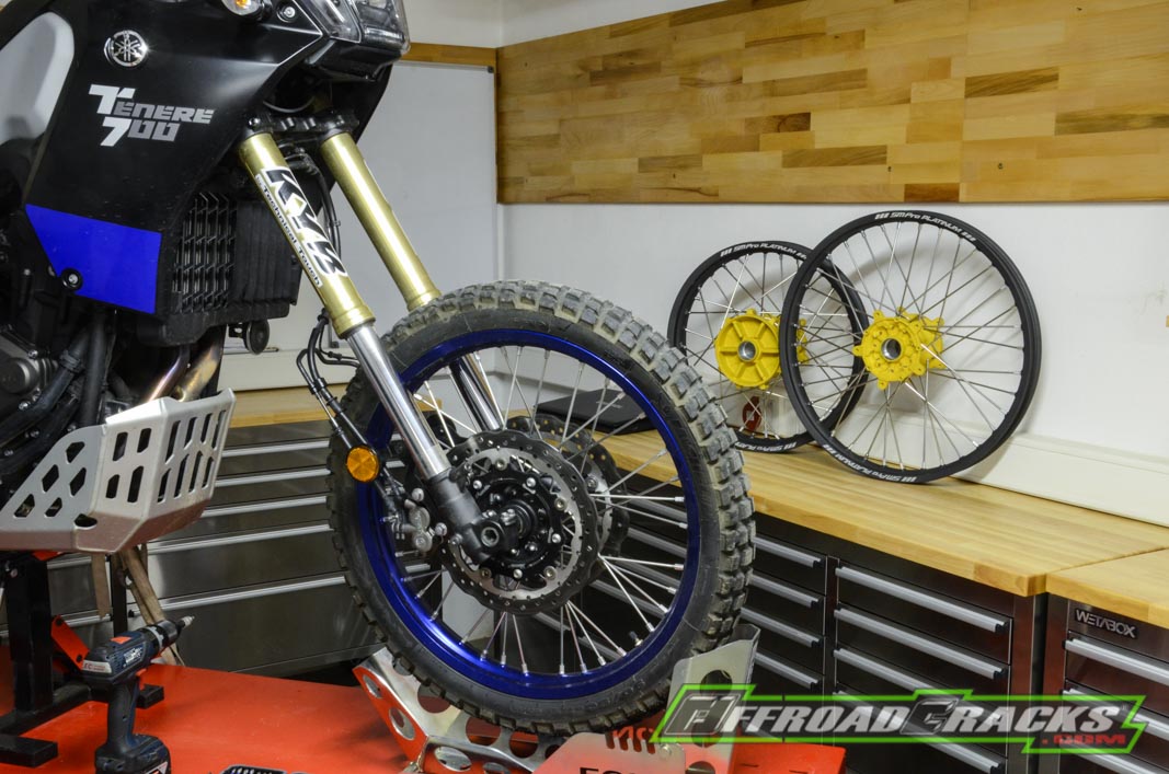
Nun kann man sich dem Radausbau widmen, der nicht wie bei einer Sportenduro üblich mit einer zu lösenden Leichtmetallschraube an der Vorderachse beginnt, sondern mit der Suche nach der passenden 19 Millimeter großen Innensechskant-Stecknuss. Wir haben hier eine aus dem vollen gefräste Leichtmetall-Universal-Lösung, die in Kombination mit einer 17er Stecknuss und Ratsche das Lösen der Vorderachse, die im linken Gabelfuß verschraubt ist, problemlos ermöglicht.
Durch die Tatsache, dass die Bremssättel schon vorher demontiert wurden ist nun das Entfernen des Vorderrads kein Problem mehr. Man sollte nur beim Herausziehen der Achse darauf achten die zwei Distanzstücke zwischen Gabelfaust und Nabe an der linken und rechten Seite des Rads gleich mit einem Kabelbinder am Rad zu befestigen. So können sie schon nicht verloren gehen oder irgendwo unter der Werkbank unbemerkt verschwinden.
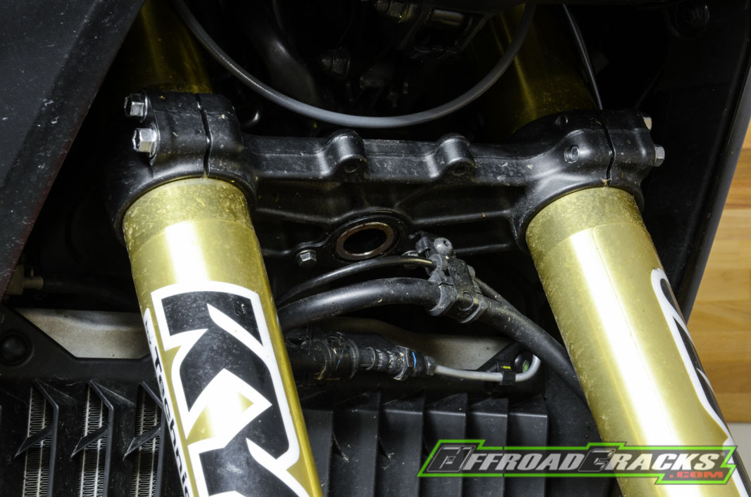
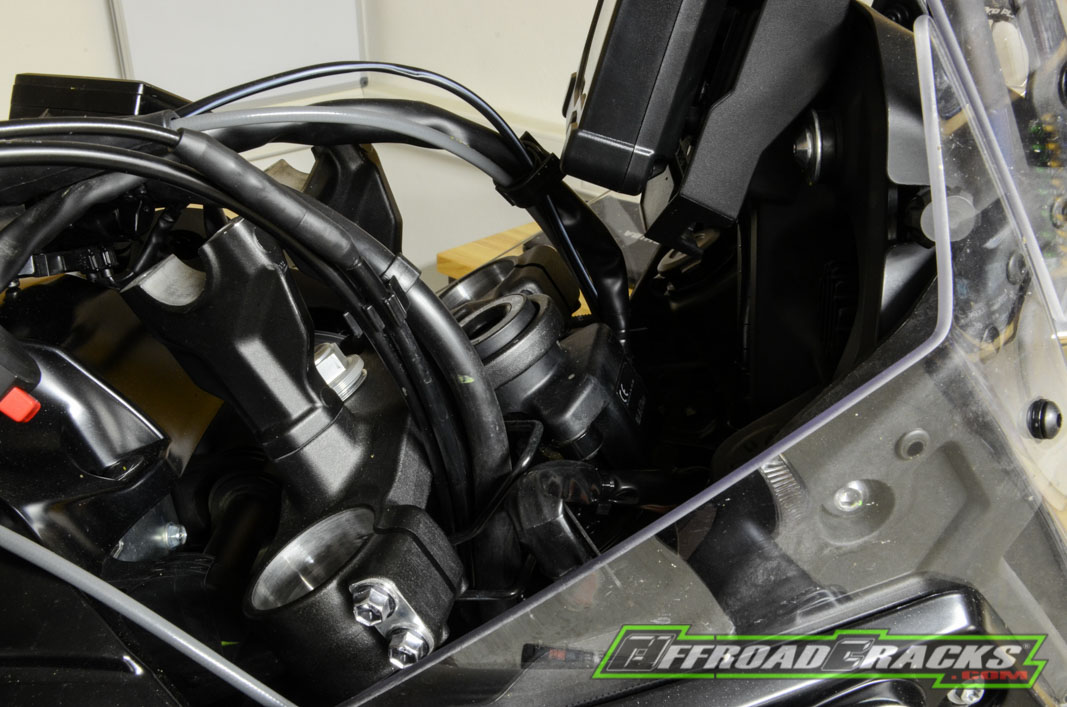
Bevor man sich nun daran macht die Klemmschrauben der Gabelbrücken zu lösen, um die Holme entfernen zu können, sollte man vorher die Verteilereinheit der Bremsleitungen lösen. Sie ist an der unteren Gabelbrücke mit zwei 8er Sechskant-Schrauben samt Gummitülle am Steuerrohr befestigt.
Anschließend löst man zuerst die Klemmschrauben an der unteren Gabelbrücke, also insgesamt vier. Anschließend die zwei unteren Klemmschrauben der oberen Gabelbrücke, wozu Letztere eine bestimmte Position haben muss, damit man mit der Ratsche samt Verlängerung agieren kann.
Die letzte Klemmschraube wird dann nach und nach vorsichtig geöffnet, während man mit der anderen Hand das Standrohr sichert, so dass es nicht nach unten unkontrolliert hindurchrutschen kann und versehentlich auf der Hebebühne aufschlägt – gleiches gilt für den zweiten Gabelholm.
Jetzt heißt es etwas Fummel-Arbeit, da das Zündschloss mit integrierter Wegfahrsperre mit zwei Sicherheitsschrauben montiert sind, die nur mit entsprechender Kenntnis durch Aufbohren oder Anschweißen einer Mutter gelöst werden können. Da wir das bereits bei der ersten Demontage durchgeführt und durch zwei 12er Sechskant-Schrauben ersetzt haben, lässt sich das Zündschloss nun auch bei demontierter oberer Gabelbrücke leicht entfernen.
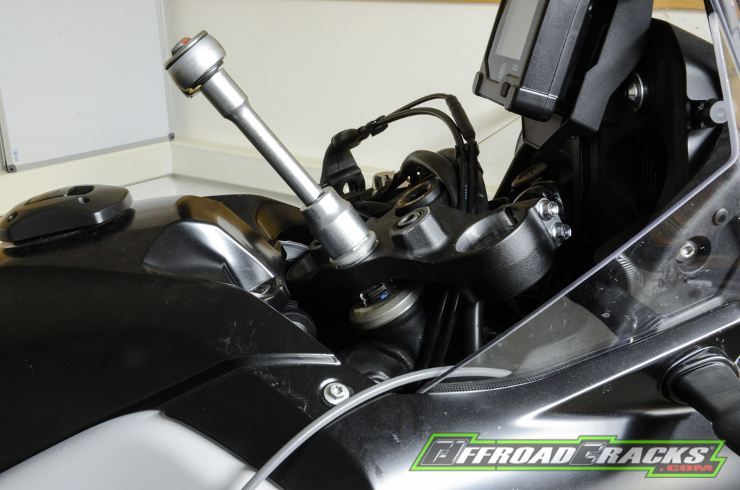
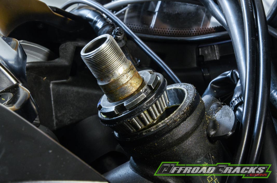
Um jedoch an die Steuerrohr-Mutter zu gelangen muss zunächst die Lenkeraufnahme entfernt werden, was nur von der Unterseite mit zwei Verlängerungen und einer 12 Millimeter Stecknuss möglich ist. Dann erst lässt sich die einteilige Guss-Lenkeraufnahmen-Einheit aus der oberen Gabelbrücke herausnehmen. Jetzt benötigt man schweres Geschütz, denn die 27 Millimeter große Lenkkopf-Mutter aus Aluminium will mit einer satt sitzenden Stecknuss gelöst werden, wozu ein gewisser Hebel notwendig wird. Hat man das geschafft, braucht man sich noch nicht vor einer herausfallenden unteren Gabelbrücke fürchten, da diese noch mit zwei Kontermuttern oberhalb des Lenkkopfs über das Schaftrohr gesichert ist. Denn über diese Kontermuttern lässt sich das Lenkkopflager-Spiel einstellen.
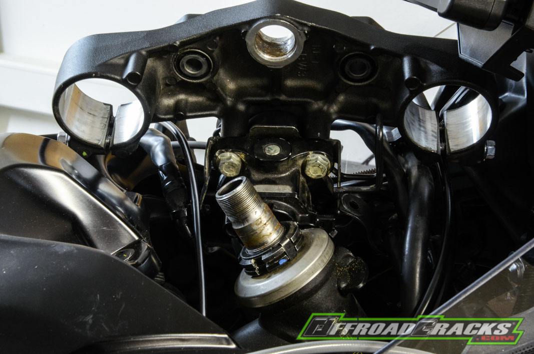
Hat man die obere Gabelbrücke abgenommen – hier und im Folgenden bitte genauestens auf die Reihenfolge und Einbaurichtung von Scheiben, Lager und Abdeckungen achten, gegebenenfalls einfach jeden Schritt fotografieren – muss ein Sicherungsblech mit seitlichen Stegen entfernt werden.
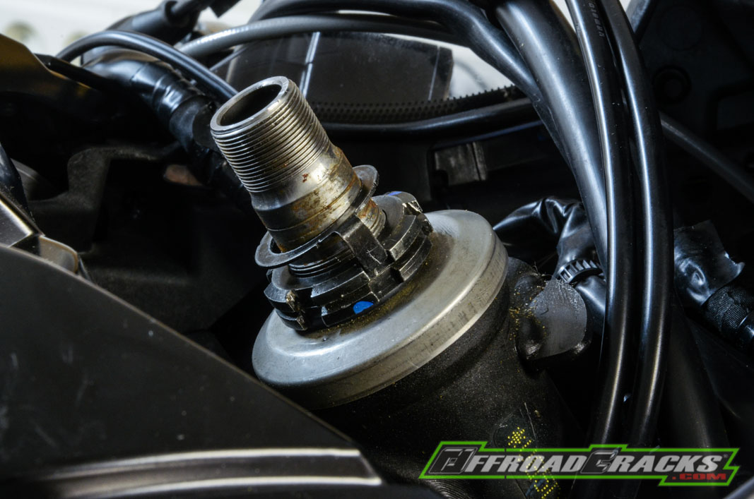
Erst dann kann man die Kontermutter im Stile der zur Einstellung der Federvorspannung am Federbein mit leichten Schlägen und Durchschlag öffnen. Berücksichtig man das, erfährt die Kontermutter kaum eine Materialverformung. Hat man sie abgenommen ist die optisch gleiche Mutter mit integrierter Alu-Schutzabdeckung fürs obere Lenkkopflager zu lösen. Jetzt muss man Achtung geben, denn hat man hier nicht die Hand an der unteren Gabelbrücke oder hat diese nicht gesichert, fällt sie nach unten ungebremst heraus. Also Stück für Stück die Mutter lösen und die untere Gabelbrücke anschließend nach unten herausziehen.
Am Besten im Anschluss sogleich alle Abdeckungen, Scheiben, Lager und Mutter samt oberer Gabelbrücke richtig vormontieren, dann gibt es beim Wiederzusammenbau kein Fragezeichen oder ein Durcheinander.
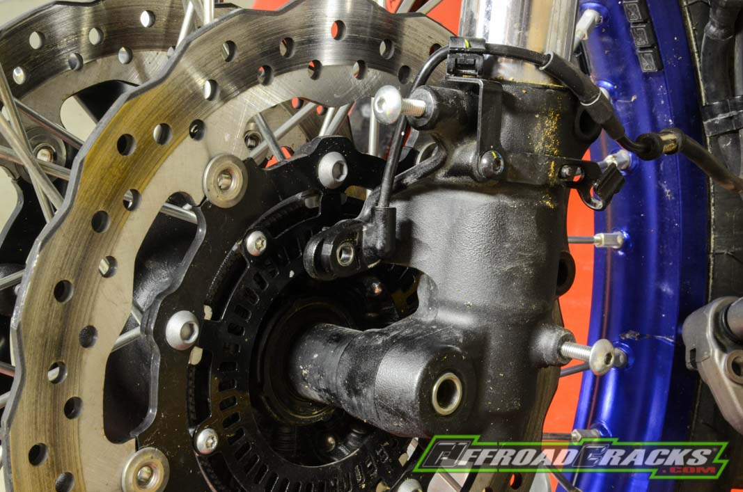
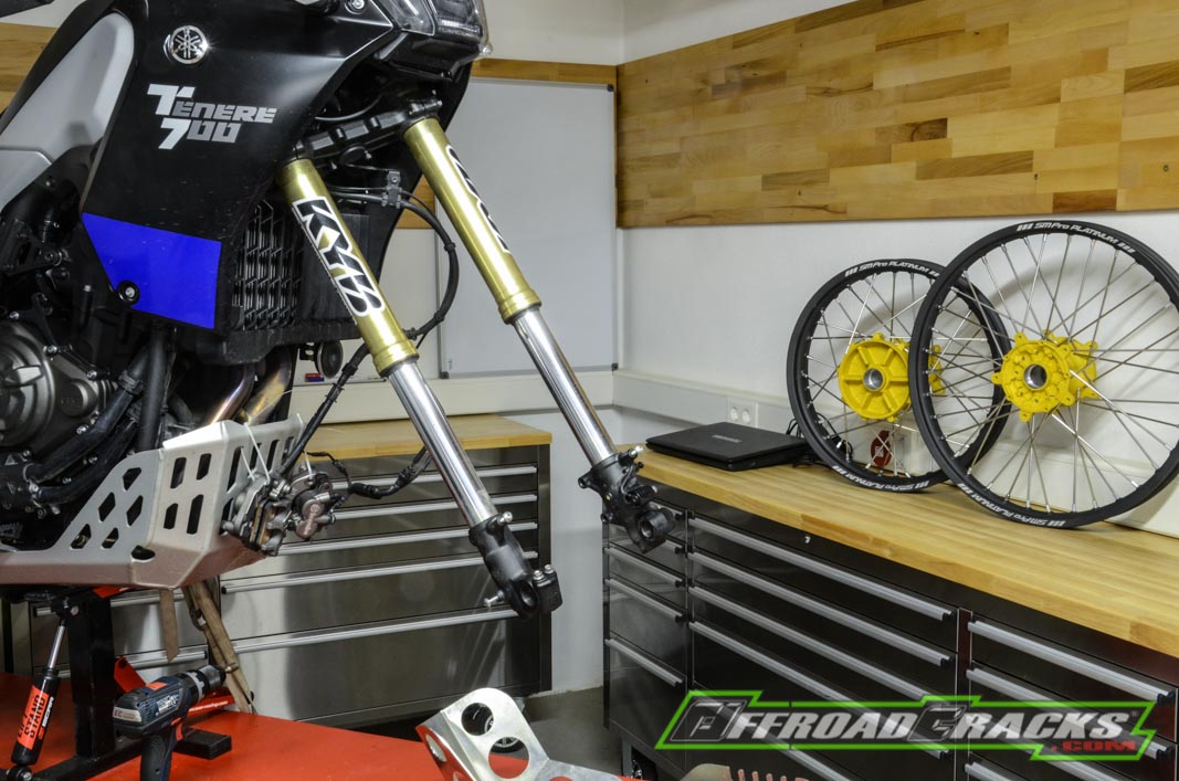
Nun kann man durchweg festhalten, dass die gesamte Vorderhand der Yamaha Ténéré 700 entfernt wurde und wir den Einbau der Xtrig-Gabelbrücke samt 48 Millimeter starken Kayaba-Upsidedown-Gabel kaum abwarten können. Doch zuvor muss noch das Bremsleitungssystem samt ABS-Element demontiert werden, was weitere Stunden an Arbeit mit sich bringt. Denn wir verbauen ein eigenständiges Bremssystem ohne ABS. Letzteres bietet keinen ABS-Ring an der Nabe, was auch im Rallye-Einsatz nicht notwendig ist – im Gegenteil. Das Mitführen einer schweren ABS-Einheit stellt nur eine zusätzliche Fehlerquelle dar, die bei Defekt nicht instand gesetzt werden kann und das vorzeitige Aus im Wettbewerb bedeutet würde. Für unsereins im Offroad-Einsatz wird das ABS schlichtweg nicht benötigt. Schöner Nebeneffekt, wir können der T7 noch ein paar Pfunde ersparen.
Für den Anwender: Hierbei handelt es sich nur um eine Hilfestellung, die sich fahrzeugspezifisch orientiert. Wer sich mit den erklärten Arbeitsschritten in Bezug auf seine eigenen Yamaha Ténéré 700 nicht hundertprozentig sicher ist oder nicht über die passenden Werkzeuge und die notwendigen Fachkenntnisse verfügt, sollte einen Fachmann zu Rate ziehen.
Weiter geht’s in Teil sechs und sieben mit weiteren Maßnahmen bis hin zur Montage der Performance-Gabel – es bleibt also interessant. Noch mehr sind wir natürlich gespannt auf die fahrerischen Möglichkeiten und das Fahrverhalten mit diesem technischen Update, sobald die Umbauß vervollständigt sind und das Wetter wieder mitspielt.
Kooperationspartner
![]()
![]()
After the presentation of the high-end wheels (LINK), it is now the turn of the fork update: Here is the first part of the modification.
For the performance update on the foreground, we will be installing a 48 mm upsidedown fork, which will receive a few technical tidbits. But before we go into the special features here, we want to bring you closer to the removal of the original fork and the installation of the performance fork in detail. In order to carry out this conversion on an adventure bike with a starting weight of 200 kilograms, a few safety measures are required, which are no less important in the case of a light sports enduro, but do not come into focus as much.
For the user: This is only an assistance that is vehicle-specific. Anyone who is not one hundred percent sure about the explained work steps in relation to their own Yamaha Ténéré 700 or does not have the appropriate tools and the necessary specialist knowledge should seek advice from a specialist.
In this case, we use a professional lifting platform with a stand, so that the wheels are relieved and we can achieve a comfortable working height. Depending on where the lift stand is attached, the Ténéré 700 T7 is automatically supported on the front wheel or the rear wheel. Because we need a free front wheel here, the T7 is again fixed to the lift via the rear wheel. Of course, securing a motorcycle on a lifting platform is always part of what we do here in the classic way by using the footpegs.
For this kind of work you should be able to fall back on a somewhat more extensive range of tools including knowledge, as removing the fork including the triple clamps on an adventure bike is a little more complex than on a sports enduro. First of all, six allen screws on the front plastic wheel cover must be removed from the T7. We use a cordless screwdriver with adjustable torque and breakaway torque so that loosening and tightening can be well controlled. The six hexagon socket screws are located on the lower fork arms and at the level of the side holders with cat eyes. Then just remove the brake lines from their plastic guides on the rear of the wheel cover.
Then you have to remove the speedo sensor, which is attached to the left fork base – in driving direction. This is well protected by a plastic protector and can easily be pulled out of its guide after removing the screw. Then the connection cable can be more easily detached from the front wheel cover so that the latter can be completely removed without having to be dismantled into its individual parts.
The next measure applies to the calipers. To do this, you should put a few cable ties aside in advance. To dismantle you need a 12 mm socket and a ratchet with a short extension to loosen the two brake caliper screws. These are usually screwed with a slightly higher torque, which is why you bring the fork left or right to the end stop so that it can no longer move itself. Before you take out the last screw, the brake calliper must be secured with a cable tie on the engine protection so that there is no undesirable pull on the brake line. The same applies to both Brembo brake calipers, of course.
Now you can devote yourself to removing the wheel, which does not begin with a light metal screw to be loosened on the front axle, as is usual with a sports enduro, but with the search for the appropriate 19 millimeter hexagon socket. We have a light metal CNC universal solution, which in combination with a 17 mm socket and ratchet enables the front axle, which is screwed into the left fork foot, to be loosened without any problems.
Due to the fact that the brake calipers have already been dismantled, removing the front wheel is no longer a problem. When pulling out the axle, you should only ensure that the two spacers between the fork leg and the hub on the left and right side of the wheel are attached to the wheel with a cable tie. That way, they can’t get lost or go unnoticed somewhere under the workbench.
Before you start to loosen the clamping screws of the triple clamps in order to be able to remove the bars, you should first loosen the distributor unit of the brake lines. It is attached to the lower triple clamp with two 8mm hexagon screws including a rubber grommet on the head tube.
Then you first loosen the clamping screws on the lower triple clamp, so a total of four. Then the two lower clamping screws of the upper triple clamp, for which the latter must be in a certain position so that the ratchet and the extension can be used.
The last clamping screw is then carefully opened little by little while the fork rod is secured with the other hand so that it cannot slide down through uncontrolled and accidentally hit the lift – the same applies to the second fork rod.
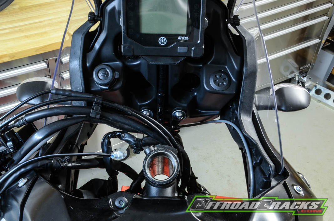
Now it means some fiddling work, because the ignition lock with integrated immobilizer is mounted with two safety screws that can only be loosened with the appropriate knowledge by drilling or welding a nut on it. Since we already did this during the first dismantling and replaced it with two 12 mm hexagon screws, the ignition lock can now be easily removed even with the removed upper triple clamp.
However, in order to get to the head tube nut, the handlebar mount must be removed first, which is only possible from the underside with two extensions and a 12 millimeter socket. Only then the one-piece cast handlebar mount unit can be removed from the upper fork triple clamp. Now you need a heavy artillery, because the 27 millimeter large steering head nut made of aluminum needs to be loosened with a well-fitting socket, which requires a certain lever. Once you’ve done that, you don’t have to worry about the lower triple clamp falling out, as it is still secured with two counter nuts above the steering head over the steering tube. Because the steering head bearing play can be adjusted via these counter nuts.
Once you have removed the upper triple clamp – here and below, please pay close attention to the order, installation direction of the washers, bearings and covers, if necessary simply photograph every step – a locking plate with side bars must be removed.
Only then can you open the lock nut in the style of adjusting the spring preload on the shock absorber with light blows. If you take this into account, the lock nut hardly experiences any material deformation. Once you have removed it, loosen the visually identical nut with an integrated aluminum protective cover for the upper steering head bearing. Now you have to be careful, because if you don’t have your hand on the lower triple clamp or have not secured it, it will fall out unbraked downwards. So loosen the nut bit by bit and then pull the lower triple clamp out downwards.
The best thing is to pre-assemble all covers, washers and nuts, including the upper fork bridge immedately, so that there is no question mark or confusion when reassembling.
Now it can be said that the entire front of the Yamaha Ténéré 700 has been removed and that we can hardly wait for the Xtrig triple clamp to be installed, including the 48 millimeter thick Kayaba upside-down fork. But first the brake line system including the ABS element has to be dismantled, which means additional hours of work. Because we install an independent braking system without ABS. The latter does not have an ABS ring on the hub, which is also not necessary in rallying – on the contrary. Carrying a heavy ABS unit is just an additional source of error that cannot be repaired in the event because of a defect and would mean an early exit from the competition. For us in off-road use, ABS is simply not needed. Nice side effect, we can save a few pounds extra.
For the user: This is only an assistance that is vehicle-specific. Anyone who is not one hundred percent sure about the explained work steps in relation to their own Yamaha Ténéré 700 or does not have the appropriate tools and the necessary specialist knowledge should seek advice from a specialist.
It continues in parts six and seven with further measures up to the assembly of the performance fork – so it remains interesting. We are of course even more excited about the driving possibilities and the driving behavior with this technical update, as soon as the conversion has been completed and the weather cooperates again.
Cooperation partners
![]()


!!!")


!!!")


